Experimental Method
TiN, TiAlN, TiN-MoS?, and CrTiAlN composite coatings were deposited on YT14 cemented carbide cutters using a closed-field unbalanced magnetron sputtering ion plating equipment from Teer Company. The nano hardness and elastic modulus of the coatings were measured using a Nano Test 600 nano hardness tester. To reduce experimental errors, the hardness and elastic modulus values were the average of five measurements. The hardness of the coatings was also verified using a Vickers microhardness tester, and the morphology and phase structure of the cutter coatings were observed and analyzed using a Quanta 200 scanning electron microscope (SEM) and an Advance 8 X-ray diffractometer (XRD). The cutting tests of the coated cutters were conducted on a CNC machining center, with PCNiMoVA steel as the cutting material. The flank wear was observed and measured using a 30x tool microscope. The cutting time when the wear strip width on the flank face exceeded 0.6mm was used as the basis for evaluating the tool’s life, and the cutting life of the tools was compared.
Experimental Results and Analysis
Coating Hardness and Elastic Modulus Testing
Figure 1 shows the loading and unloading curves obtained during the nano hardness measurement process of the CrTiAlN composite coating. The loading and unloading curves not only provide the hardness of the CrTiAlN film but also its elasticity. Define R = (ha – h) / h as the elastic recovery coefficient, where ha is the indentation depth at maximum load, and h is the residual depth of the indentation after unloading. According to the definition of R, the greater the value of R, the greater the elasticity of the film. Therefore, based on the nano indentation curve in Figure 1, the hardness of the CrTiAlN film is 33 GPa, and the elastic modulus is 675 GPa. Figure 2 is a comparative analysis chart of the nano hardness of TiN, TiAlN, TiN-MoS?, and CrTiAlN coatings. It can be seen from the figure that the nano hardness measurement values of the four coatings are 18 GPa, 30 GPa, 15 GPa, and 33 GPa, respectively. The nano hardness ranking is as follows: CrTiAlN > TiAlN > TiN > TiN-MoS?.
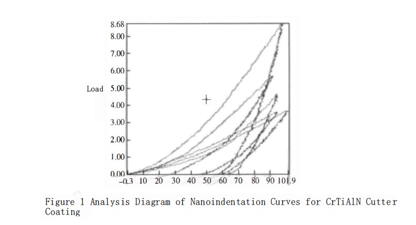
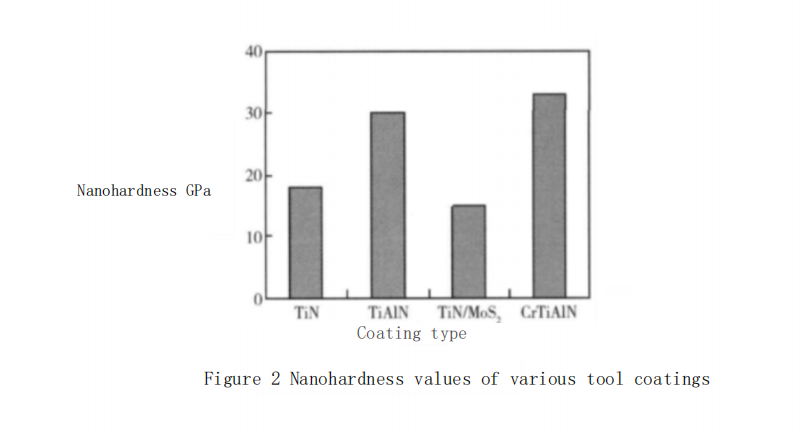
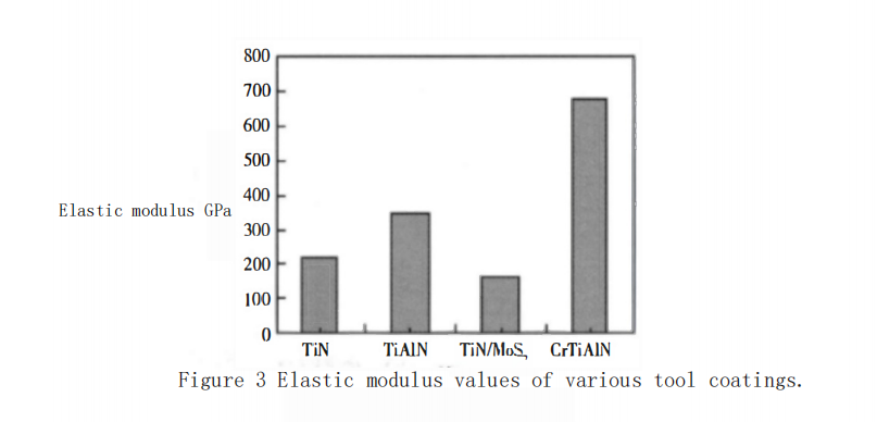
Figure 3 shows the measured elastic modulus values of each coating. It can be seen from the figure that the elastic modulus of the four coatings are 214 GPa, 346 GPa, 164 GPa, and 675 GPa, respectively. The ranking of the elastic modulus is as follows: CrTiAlN > TiAlN > TiN > TiN-MoS?. This indicates that the elastic modulus of the coatings is directly proportional to their hardness. However, the CrTiAlN coating shows the greatest relative increase in elastic modulus, with a value significantly higher than other coatings, reaching 675 GPa, which suggests that the deposited CrTiAlN coating has both high hardness and high elasticity.
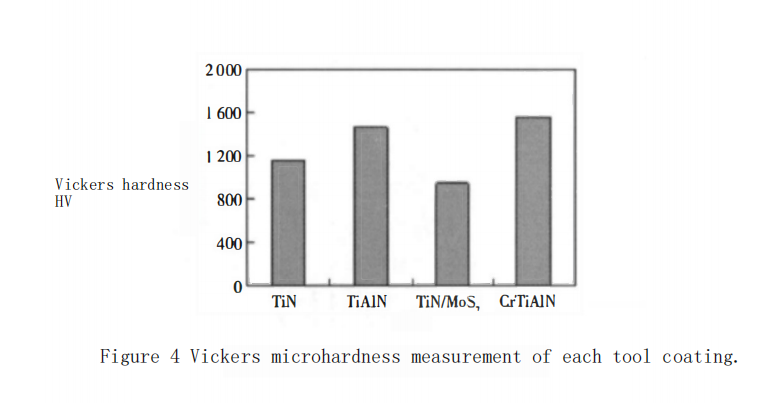
Meanwhile, the Vickers microhardness tester was used to perform microhardness verification tests on each cutter coating, with a indentation load of 15g and a duration of 10 seconds. The measurement results are shown in Figure 4. By comparing the coating nano hardness in Figure 2 with the coating microhardness values in Figure 4, it can be found that the microhardness variation trend of each coating is the same as the nano hardness variation trend, with the CrTiAlN coating having the relatively highest Vickers microhardness at HV1560.
Analysis of Coating Surface Morphology
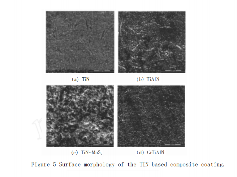
The surface morphologies of the TiN, TiAlN, TiN-MoS?, and CrTiAlN coated cutters are shown in Figure 5. It can be observed from the figure that there is a significant difference in the surface morphology of the four coatings, indicating that the addition of composite elements has caused a great change in the crystalline state of the TiN compounds. Among them, the TiN coating surface phase tissue is uniform, with relatively fine particles, while the TiAlN coating surface morphology is relatively rough, with coarser particle tissue. The TiN-MoS? coating surface is distributed with a large amount of flaky mixed structure, mainly due to the uniform distribution of MoS? phase in the TiN coating, tending towards a composite structure in the mixed state, which serves a self-lubricating function. The CrTiAlN coating surface grains are relatively fine, the coating is dense and uniform, and the surface is distributed with a large number of hard points.
Drilling Test
The four types of coated cemented carbide cutters were used to machine PCNiMoVA steel, and the wear condition of the cutters was inspected to compare the durability of different coated cutters.
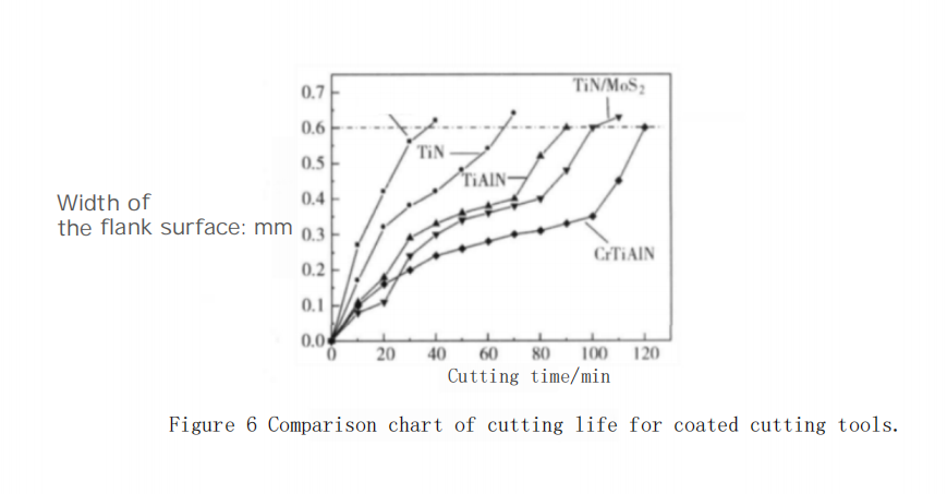
The cutting test conditions for the coated cutters were as follows: the cutting method was external cylindrical cutting, the cutting speed was 160 m/min, the feed rate was 0.15 mm/r, the cutting depth was 0.5 mm, and dry cutting was performed. The cutting time when the wear strip width on the flank face exceeded 0.6 mm was used as the basis for evaluating the tool’s life, and the cutting life of the tools was compared.
A comparison of the cutting life of the coated cutters is shown in Figure 6.
From the figure, it can be seen that under dry cutting conditions, the cutting life of the uncoated cutters was the shortest, and the service life of the coated cutters was significantly better than that of the uncoated cutters. Among them, the CrTiAlN coated cutter had the longest cutting life. The ranking of the cutting life of the four coated cutters was as follows: CrTiAlN > TiN-MoS? > TiAlN > TiN. This indicates that Cr and Al elements form hard phases in the TiN coating, and the addition of Al elements is beneficial for the formation of Al oxides, which avoids further oxidation during the cutting process, improves the oxidation resistance of the cutters, and is conducive to increasing the cutting life of the tools. Meanwhile, the MoS? lubricating phase helps to reduce the friction coefficient of the cutters, improve the anti-wear capability of the tools, and also extends the service life of the cutters.
In summary, due to the comprehensive utilization of the advantages of various coating components in the multi-component composite coatings, they achieve better comprehensive performance, ensuring excellent wear resistance and toughness, reducing the formation of built-up edge, and possessing mechanical shock and thermal shock resistance, which can greatly improve the tool life.
XRD Test Analysis
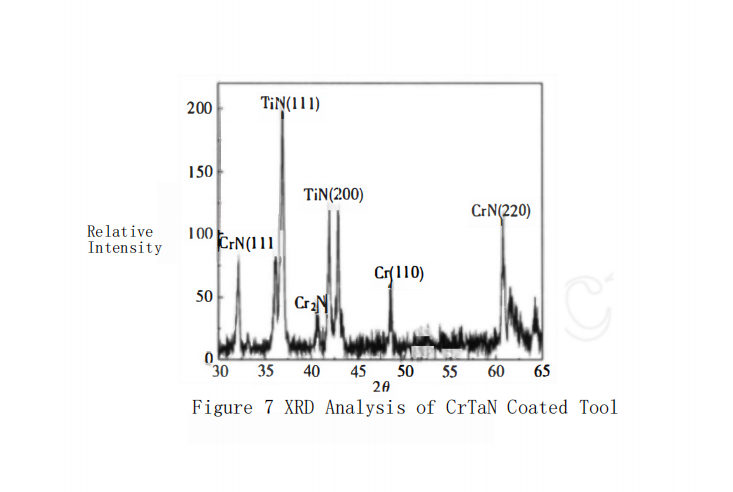
XRD analysis method was used to characterize the phase structure of the CrTiAlN tool coating with the best cutting performance, and the results are shown in Figure 7. The XRD spectrum analysis indicates that the crystal phases of the coating are mainly composed of Cr, CN, CEN, and TiN at room temperature, and the amorphous phase in the coating was not detected. At the same time, high magnification scanning analysis of the tool coating revealed a large number of hard phase particles distributed on the coating surface. Combined with X-ray diffraction analysis, it is known that these hard phases are mainly CN, CrN, TiN, and AlN phases. These hard phases are beneficial for improving the cutting life of the coated cutters.
Вывод
The author has prepared TiN, TiAlN, TiN-MoS?, and CrTiAlN composite coatings using a closed-field unbalanced magnetron sputter ion plating PVD coating process. Comparative tests on the mechanical properties and cutting performance of the coatings show that:
The nanoindentation analysis obtained the nano hardness ranking of the four types of cutter coatings as follows: CrTiAlN > TiAlN > TiN > TiN-MoS?. The elastic modulus of the coatings is directly proportional to their hardness.
Under dry cutting conditions, when drilling PCNiMoVA steel, the cutting life of the coated cutters is ranked as: CrTiAlN > TiN-MoS? > TiAlN > TiN. This indicates that the cutting performance of the multi-component composite coatings is significantly better than that of the simple TiN coating, suggesting a direction for the future development of coated cutters.


