Selection Criteria for Cutting-in Methods
In the actual machining process, selecting an appropriate cutting-in method for end mills requires comprehensive consideration of multiple factors. First, the characteristics of the workpiece material, such as hardness and toughness, are crucial. For materials with low hardness, vertical cutting-in can be appropriately considered; for materials with high hardness and great toughness, gentle cutting-in methods such as oblique cutting-in or spiral cutting-in should be prioritized.
Pre-drilling
Pre-drilling a hole in the workpiece (5 – 10% larger than the diameter of the end mill) is the safest way to insert the milling cutter. This method can prevent premature wear of the tool. Chip evacuation is smoother, thus reducing the risk of chip accumulation and tool breakage. This method is usually employed when machining materials prone to built-up edges, ensuring consistent machinability.
Vertical Cutting-in
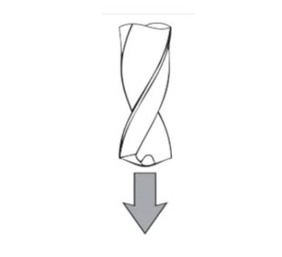
Vertical cutting-in is the most basic and common cutting-in method for end mills. This method refers to the end mill directly cutting in perpendicular to the workpiece surface. It is simple to operate and convenient for programming, and is widely used in rough machining with low requirements for machining accuracy and low material hardness. For example, when performing preliminary contour machining on aluminum workpieces, vertical cutting-in can quickly remove a large amount of material. However, vertical cutting-in also has obvious disadvantages. Since the cutting edge of the end mill is subjected to a large impact load at the moment of vertical cutting-in, it is prone to aggravate tool wear and even cause edge chipping. In addition, the large cutting force generated during vertical cutting-in may cause vibration of the workpiece, affecting the quality of the machined surface. Therefore, vertical cutting-in is not suitable for machining materials with high hardness or in cases where high requirements are placed on machining accuracy and surface quality.
Oblique Cutting-in
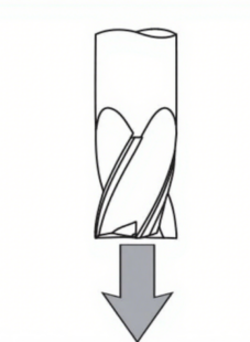
Oblique cutting-in is a relatively gentle cutting-in method. The end mill cuts into the workpiece along an oblique line at a certain inclination angle (typically between 3° and 15°). Compared with vertical cutting-in, this cutting-in method can effectively reduce the impact at the moment of tool cutting-in, lower the peak value of cutting force, and reduce tool wear. Meanwhile, oblique cutting-in can make the cutting process more stable, which is conducive to improving the quality of the machined surface.
Recommended Angles: For hard/ferromagnetic materials: 1°-3°
For plastic/non-ferromagnetic materials: 3°-10°
When machining high-hardness materials such as cast iron, the oblique cutting-in method demonstrates obvious advantages. By gradually cutting into the workpiece, the cutting edge of the end mill comes into contact with the material step by step, avoiding the severe impact of vertical cutting-in and extending the service life of the tool. In mold machining, for some complex cavities, oblique cutting-in is also commonly used in the roughing stage to improve machining efficiency and tool durability.
?Spiral Cutting-in
Spiral cutting-in is a more advanced and efficient cutting-in method. When the end mill cuts into the workpiece, it gradually penetrates along a spiral trajectory, similar to the drilling principle of a drill bit. The advantages of spiral cutting-in are remarkable: it enables the tool to maintain a continuous cutting state during the cutting-in process, with uniform distribution of cutting force, which greatly reduces the impact and vibration on the tool.
Spiral cutting-in is widely used in machining high-hardness alloy materials such as titanium alloys and nickel-based alloys. Due to the poor cutting performance of these materials, traditional cutting-in methods easily cause rapid tool wear and damage. In contrast, spiral cutting-in can effectively reduce the cutting temperature, minimize friction between the tool and the workpiece, and thus improve machining efficiency and quality.
Programming Note: When using this method, the programmed diameter should be 110-120% larger than the diameter of the cutting insert. Additionally, spiral feed has advantages in achieving precise surface finish, making it the preferred choice for high-precision and high-surface-quality machining in industries like aerospace and medical device manufacturing.
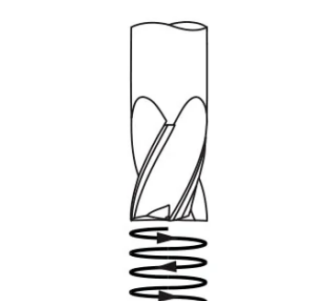
Arc Cutting-in
Arc cutting-in is a method where the end mill cuts into the workpiece along an arc trajectory. This cutting-in approach is mainly used for machining contours or surfaces with special requirements, enabling the tool to maintain a stable cutting state during both cutting-in and cutting-out. It reduces tool engagement marks on the machined surface and improves surface finish. When machining complex curved parts such as cams and blades, the arc cutting-in method can precisely control the tool’s movement trajectory to ensure machining accuracy. Additionally, during contour milling, arc cutting-in avoids over-cutting or under-cutting caused by sudden changes in cutting force at corners, making the machined contour smoother and more accurate.
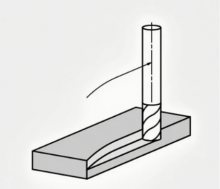
Rolling Cut
Rolling entry into the cut ensures that the tool can fully penetrate and naturally achieve an appropriate chip thickness. In this case, the feed rate should be reduced by 50%. Rolling tool engagement is particularly advantageous in slotting and contour machining, where maintaining consistent chip thickness is crucial for surface finish and dimensional accuracy. Machinists often use this method in high-speed cutting operations to maximize material removal rate while minimizing tool wear and heat generation.
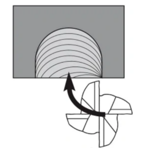
Second, machining accuracy and surface quality requirements are also important reference factors. If high requirements are placed on the surface finish and accuracy of the machined part, vertical cutting-in should be avoided, and methods ensuring stable cutting such as arc cutting-in or spiral cutting-in should be chosen. Additionally, factors such as the performance of machining equipment, the type and size of tools, and machining costs need to be incorporated into the consideration.
Selection Between Climb Milling and Conventional Milling
Principles of Climb Milling and Conventional Milling
Climb milling?refers to the scenario where the rotation direction of the milling cutter is the same as the feed direction of the workpiece, and the cutting thickness gradually decreases from maximum to zero. During climb milling, the cutting edge first contacts the machined surface of the workpiece, then cuts into the material, and the chip thickness continues to decrease as cutting proceeds.
Conventional milling?is when the rotation direction of the milling cutter is opposite to the feed direction of the workpiece, and the cutting thickness gradually increases from zero. During conventional milling, the cutting edge slides on the workpiece surface for a certain distance before cutting into the material, with the chip thickness increasing from thin to thick.
Advantages and Disadvantages of Climb Milling and Conventional Milling
Advantages of climb milling
The cutting process is relatively stable, and tool wear is relatively small. Since the chip thickness decreases from large to small, the cutting edge is subjected to less impact during cutting. Meanwhile, the vertical component of the cutting force always presses against the worktable, helping to reduce workpiece vibration and improve the surface quality of the machined part, especially suitable for finishing. However, climb milling has high requirements for machine tools: the feed mechanism of the machine tool must have a function to eliminate clearance; otherwise, under the action of cutting force, the worktable may move abruptly, affecting machining accuracy or even damaging the tool.
Advantages of conventional milling
It has lower requirements for machine tools and does not require special clearance elimination devices. During conventional milling, the horizontal component of the cutting force is opposite to the feed direction, which can effectively prevent abrupt movement of the worktable. However, during conventional milling, the cutting edge needs to slide on the workpiece surface first, which aggravates tool wear and generates more cutting heat. The surface quality of the machined part is inferior to that of climb milling, so it is generally used for rough machining or when the machine tool rigidity is insufficient.
Key Points for Selecting Climb Milling or Conventional Milling
Selecting between climb milling and conventional milling requires comprehensive consideration of factors such as workpiece material, machining accuracy requirements, and machine tool performance. For materials with low hardness and good plasticity such as aluminum and copper, as well as for finishing with high surface quality requirements, climb milling is often the better choice; for steels with high hardness, or when the machine tool rigidity is poor and there is no clearance elimination device, conventional milling is more appropriate. Additionally, when machining castings with hard skins, conventional milling can avoid the cutting edge directly contacting the hard skin and accelerating wear.
Резюме
There are various cutting-in methods for концевая фрезаs, each with its unique characteristics and application scenarios. Mechanical machining practitioners need to deeply understand the principles, advantages, and disadvantages of various cutting-in methods, as well as climb milling and conventional milling. According to actual machining needs, they should comprehensively consider multiple factors to reasonably select the cutting-in method and milling method for end mills, so as to achieve efficient and precise machining and improve product quality and production efficiency. With the continuous development of machining technology, the cutting-in methods and milling methods for end mills will also continue to innovate and optimize, bringing more possibilities to the mechanical machining industry.
Добавить комментарий
Ваш адрес email не будет опубликован.

