Wire drawing process parameters and dies
Die Material: Cemented Carbide Wire hardness: 65#
Lubricant: Soap Powder
Drawing Speed: 150 m·min?1
Inlet Diameter: 4.6 mm
Outlet Diameter: 4.2 mm
Production Volume: Approximately 12 tons
Take a set of five normally worn cemented carbide wire drawing dies that have failed due to wear. Cut them along the die hole axis using wire cutting, and clean the residual substances on the die hole surface with carbon tetrachloride. Observe the wear morphology of the die hole. Select a typical one from them and mill away most of the die sleeve to facilitate placement during observation with a scanning electron microscope and for energy spectrum analysis.
Analysis of the Wear Morphology of the Wire Drawing Die
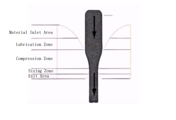
Based on the shape of the wire drawing die hole and its wear morphology, it can be divided into four regions (see Figure 1), namely the entrance zone, the transition zone between the entrance zone and the compression zone, the compression zone, and the sizing zone.
Taking the wire drawing dies from a steel rope factory that have failed due to wear during wire drawing as samples, this paper analyzes the wear morphology and main wear forms of cemented carbide wire drawing dies, providing a basis for the rational design and use of drawing dies to extend their service life.
Entrance Zone
The surface of the die entrance zone is relatively smooth, with the bonded WC particles being almost completely coated, and the surface is relatively intact. There are no extensive friction and wear marks, only a few pits left by grinding.
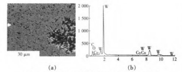
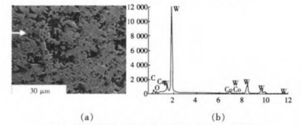
Under high magnification SEM images (see Figure 2(a)), it can be observed that there are a small number of scratch marks at some positions in the die entrance zone when the wire is being drawn through. It is evident that during the wire drawing process, the entrance zone does not come into contact with the wire, the compressive stress is low, and the wear is not significant, but it is prone to a small amount of scratching.
From the EDS analysis results (see Figure 2(b)), the surface of the die hole in this area contains not only the basic elements C, W, and Co but also a small amount of oxygen (O) elements.
Transition Zone between the Entrance Zone and the Compression Zone
In the transition area between the entrance zone and the compression zone, along the circumferential surface of the die hole, some parts are smoother while others are rougher. The smooth parts are similar to the surface morphology of the entrance zone, while the rough parts are closer to the compression zone, indicating that during wire drawing, the axis of the wire drawing die does not align with the die hole, resulting in the die at the entrance contacting the steel wire along one side, leading to uneven wear.
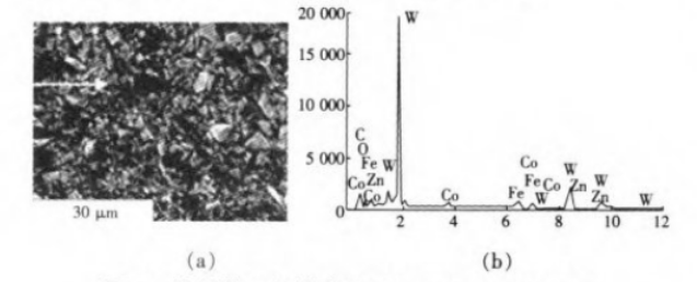
Under low magnification, the smooth surface parts are less even than the entrance zone, with an increased number of pits on the surface. Observing under high magnification SEM, as shown in Figure 3(a), the adhesive phase and skeleton particle shedding are more obvious, with wear traces scattered everywhere.
EDS analysis shows that the surface of the die hole in this area contains not only the basic elements C, W, and Co but also a small amount of oxygen (O) elements, as seen in Figure 3(b).
Compression Zone
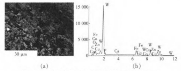
The surface is almost entirely composed of continuous protrusions and pits, making the entire surface rough. Under high magnification SEM, as shown in Figure 4(a), the binder phase Co on the die surface is almost completely extruded, and the entire surface layer consists of W and C skeleton particles, with significant particle shedding and wear. According to the EDS analysis results in Figure 4(b), the surface of the die hole in this area contains not only the basic elements C, W, and Co but also foreign elements O, Fe, and Ca.
Sizing Zone
The transition part between the sizing zone and the compression zone has worn down, and the length of the sizing zone after wear exhibits a?fact?where one side is longer than the other along the die hole surface, further indicating that the wire at the exit is not concentric with the die hole. Under low magnification SEM, the entire sizing area surface appears rough, with the morphology mainly characterized by wear stripes parallel to the drawing direction, as shown in Figure 5(a).
Under high magnification SEM, the binder phase Co is also almost completely extruded, leaving mostly W and C skeleton particles on the entire surface, accompanied by furrow-like wear morphology, with the furrows parallel to the drawing direction, as shown in Figure 5(b). According to the EDS analysis results, similar to the compression zone, the die hole surface in this area contains not only the basic elements C, W, and Co but also foreign elements O, Fe, Ca, and P.
Analysis of the Wear Mechanism of the Wire Drawing Die
Abrasive Wear
The uneven, convex-concave morphology on the die hole compression zone is primarily caused by abrasive wear. The process of abrasive wear in cemented carbide can be detailed as follows: ① movement of the binder phase on the alloy surface layer; ② plastic deformation of the binder phase; ③ increase in plastic strain of W and C grains; ④ fracture of individual W and C grains; ⑤ intergranular fracture; ⑥ grains being pulled out from the matrix.
During the steel wire drawing process, the normal stress on the die hole compression zone gradually decreases from the entrance end to the exit end. However, for drawing high-strength steel wire #65, the stress values at each point are quite high. Under the action of surface normal stress and frictional force, the binder phase Co within a certain depth of the material contact surface undergoes plastic deformation and micro-abrasive wear, resulting in the extrusion of the surface Co from between the grains and the formation of an uneven morphology. As the binder phase is lost, the surface integrity of the cemented carbide is damaged, the skeleton becomes unstable, and cracks form between the grains, causing some W and C particles to fall off from the matrix surface, creating pits on the die hole surface.
Oxidation Wear
During the steel wire drawing process, the heat generated by deformation work and friction work causes the temperature of the steel wire itself to rise, typically reaching up to 200°C. On a continuous wire drawing machine, without cooling measures, after multiple draws, the accumulated temperature of the steel wire can reach 500~600°C. It is evident that the cemented carbide wire drawing die gradually oxidizes due to working at higher temperatures. According to EDS analysis, a certain amount of oxygen (O) elements is present in various regions of the die hole surface, and the content of O elements is consistent with the distribution of the die wall temperature, with the highest in the compression zone, followed by the sizing zone, and the least in the entrance zone.
Adhesive Wear
According to EDS analysis, there are elements of Fe and lubricant components on the die hole surface, indicating the presence of adhesive wear.
Adhesive wear is mainly related to high contact stress and significant sliding. When the drawing metal comes into contact with the die surface, microscopically, the actual contact area is only on some isolated peaks. Additionally, the high normal pressure in the die hole during drawing results in enormous contact stress on these peaks. Even with the presence of a lubricant, the contact is in a boundary lubrication state. Under the combined action of the drawing force and the die hole pressure, the temperature rises, the lubricating film breaks, the peaks undergo plastic deformation, and adhesion, welding, and tearing occur, leading to metal transfer and adhesion to the die surface.
Conclusione
(1) The most severe wear areas of the wire drawing die hole are the compression zone and the sizing zone, with the main wear mechanisms being abrasive wear, oxidation wear, and accompanied by adhesive wear. Therefore, to reduce the wear of cemented carbide wire drawing dies, efforts should be made to reduce abrasive wear, oxidation wear, and adhesive wear.
(2) The misalignment of the steel wire at the entrance and exit of the die hole with the die hole axis can lead to uneven radial wear of the die hole. Therefore, it is important to properly straighten the wire before drawing and ensure that the wire entry direction is as aligned as possible with the wire drawing die axis to reduce uneven radial wear of the die hole, which can cause premature die failure.

