Structural Types
carbide?face milling cutters can be categorized into three types: integral welding type, mechanical clamping ?type, and indexable type.
The diagram 1 below illustrates an integral welding type face milling cutter. This type has a compact structure and is relatively easy to manufacture. However, if the teeth are damaged, the entire milling cutter must be discarded, so its usage has decreased.
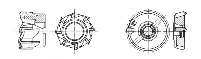
As shown in the above diagram is the mechanical clamping welding type face milling cutter. This cutter welds carbide?inserts onto small cutter heads, which are then mechanically clamped into slots on the cutter body. When the inserts are worn out, they can be replaced with new ones, thereby extending the cutter body’s service life.
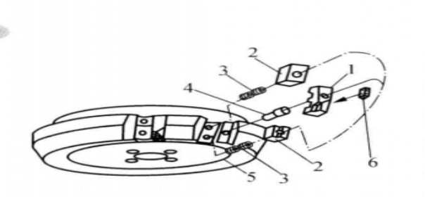
As shown in Figure 2, the commonly used indexable face milling cutter consists of components such as the cutter body (5), insert (1), tightening screws (3), cutter blade (6), wedge block (2), and eccentric pin (4). The insert (1) is clamped onto the cutter body using the wedge block (2) and tightening screws (3). Before tightening the screws, the eccentric pin (4) is rotated to adjust the axial runout of the insert within a specified range at the axial support point. Once the cutter blade (6) is mounted on the insert, it is clamped in place by the wedge block (2) and tightening screws (3). The eccentric pin (4) also prevents excessive axial forces on the insert during cutting, thereby preventing axial movement.
Compared to high-speed steel face milling cutters, carbide?face milling cutters offer higher milling speeds, better processing efficiency, and improved surface quality. They are capable of machining workpieces with hardened surfaces and layers, demonstrating significant advantages in enhancing product quality and processing efficiency.
Face Milling Cutter Main Structural Parameters
(1) Diameter and Number of Teeth
Diameter and number of teeth are the two main structural parameters of a face milling cutter. To accommodate different cutting requirements, face milling cutters of the same diameter are classified into coarse, medium, and fine types based on the number of teeth. Taking a 100 mm diameter cutter as an example, the number of teeth for coarse, medium, and fine types are 5 teeth, 6 teeth, and 8 teeth respectively.
(2) Geometric Angles
Indexable face milling cutters have key geometric angles including the lead angle κr, rake angle γp, and clearance angle γf. The lead angle κr is available in 45°, 60°, 75°, and 90° variants, with 75° being the most commonly used. When machining flat surfaces with shoulders or thin-walled workpieces, a 90° lead angle is typically chosen.
The rake angle γp and clearance angle γf can be combined into positive rake, negative rake, and positive-negative rake configurations. Positive rake angles are used for machining general materials; for instance, γp=7° and γf=0° are common for milling mild steel and cast iron, while γp=18° and γf=11° are used for milling aluminum alloys. Negative rake angles are employed for machining cast steel and hard materials, often set at γp=-7° and γf=-6°. Positive-negative rake angles offer good impact resistance and chip removal properties, suitable for milling general steel and cast iron, commonly used on machining centers with values like γp=12° and γf=-8°.
How to Select a Face Milling Cutter?
Selection of Face Milling Cutter Diameter
(1) When the machining area is not large, it is important to choose a tool or milling cutter with a diameter larger than the width of the plane. This allows for single-pass face milling. When the width of the face milling cutter is 1.3 to 1.6 times the width of the machining area, it effectively ensures proper chip formation and removal.
(2) For machining large surface areas, it is necessary to select a milling cutter with an appropriate diameter and perform multiple passes for face milling. Due to machine limitations, cutting depth, width, and the dimensions of the cutter and inserts, the diameter of the milling cutter may be constrained.
(3) When machining small plane areas or dispersed workpieces, a smaller diameter end mill should be selected for milling. To achieve optimal efficiency, the milling cutter should have contact with the workpiece equal to 2/3 of its diameter, which means the milling cutter diameter should be 1.5 times the width of the cut. Properly using this ratio of cutter diameter to cutting width ensures the milling cutter approaches the workpiece at an ideal angle. If the machine’s power cannot sustain cutting at this ratio, axial cutting thickness can be divided into two or more passes to maintain the ratio of cutter diameter to cutting width as much as possible.
Selection of Number of Teeth on the Milling Cutter
When selecting a milling cutter for machining, the number of teeth is an important consideration. For example, a coarse-toothed milling cutter with 6 teeth has a diameter of 100 mm, whereas a fine-toothed milling cutter with 8 teeth also has a diameter of 100 mm. The density of teeth affects both production efficiency and product quality. Dense teeth improve efficiency and quality but may hinder chip removal. Depending on the diameter of the teeth, they can be categorized as sparse teeth, fine teeth, and dense teeth.
Sparse teeth are used for rough machining of workpieces, with 1 to 1.5 inserts per 25.4 mm diameter, providing ample space for chips. Such tools are suitable for continuous chip formation in soft materials, using long blades and wide cuts. Dense teeth are advantageous for stable machining conditions, typically used for rough machining of cast iron, shallow and narrow cuts in high-temperature alloys, and when chip space is not required.
Dense teeth are applied in fine milling, with axial cutting depths ranging from 0.25 to 0.64 mm per tooth, minimizing cutting loads and power requirements, suitable for machining thin-walled materials.
Selection of Milling Inserts
The choice of milling inserts for flat milling is a critical factor to consider. In certain machining scenarios, pressed inserts are more suitable, while in others, ground inserts are preferred.
For rough machining
Pressed inserts are often preferred as they lower machining costs. Pressed inserts have lower dimensional accuracy and edge sharpness compared to ground inserts. However, they offer better edge strength, making them suitable for rough milling tasks. They can withstand higher impact and accommodate larger depths of cut and feed rates. Pressed inserts typically feature chip grooves on the front face, reducing cutting forces and friction with the workpiece and chips, thereby lowering power requirements. However, their surface finish is less compact than ground inserts, resulting in varying heights among insert tips on the milling cutter body. Due to their cost-effectiveness, pressed inserts find widespread use in production.
For fine milling
Ground inserts are preferable due to their superior dimensional accuracy. This high precision ensures precise positioning of the cutting edge during milling, leading to higher machining accuracy and lower surface roughness values. Moreover, the trend in ground milling inserts for fine machining includes forming large positive rake cutting edges with chip grooves, allowing the inserts to handle small feed rates and depths of cut effectively. In contrast, carbide?inserts without sharp rake angles may experience friction with the workpiece during fine machining with small feed rates and depths of cut, reducing tool life.


