- Flank wear and crater wear
- Built-up edge (BUE)
- Microchipping
-
Contenido ocultar
Crater Wear
- Thermal mechanical failure
- Plastic deformation
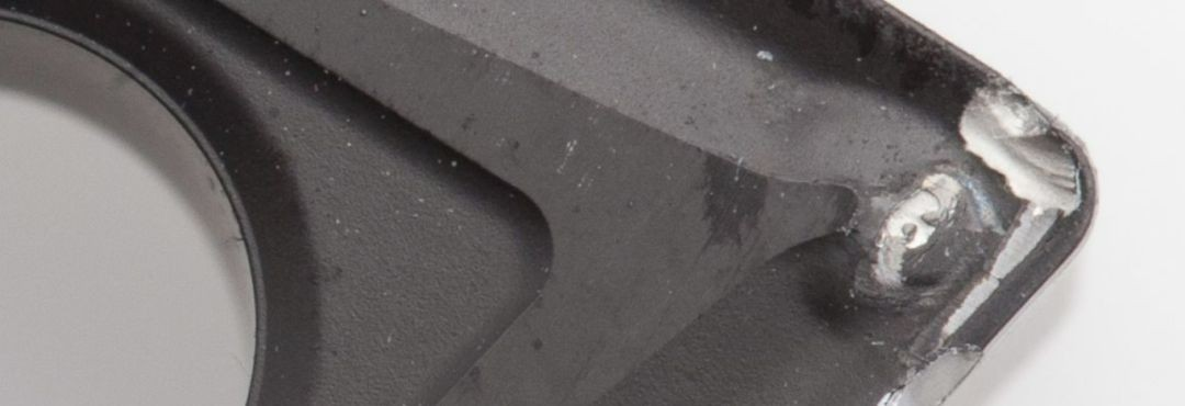
For these tool failure types, we provide some possible strategies to avoid or at least minimize their impact on the machining process.
1.Flank Wear Analysis
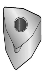
In machining, flank wear is the most common and desirable type of tool wear. It is the easiest to identify and predict among tool failure types. Flank wear typically occurs uniformly and gradually as the cutting edge wears away with machining material, resembling dulling of the edge.
When Does Flank Wear Occur?
During machining, flank wear typically occurs under the following conditions: At lower cutting speeds, flank wear is mainly caused by abrasive and adhesive wear. Hard abrasive particles in the workpiece material can scrape the tool surface. Subsequently, fragments of the tool coating may detach, further scratching the cutting edge.
Other elements such as cobalt eventually wear off from the tool substrate, reducing the adhesion of hard alloy particles, making them prone to detachment. At higher cutting speeds, diffusion wear becomes the primary cause of flank wear as high-speed cutting generates cutting heat providing favorable conditions for diffusion phenomena. Flank wear typically manifests as uniform wear along the cutting edge of the tool. Sometimes, workpiece material may smear on the cutting edge, which may exaggerate the visual size of wear scars. Rapid wear is common when machining wear-resistant materials such as nodular cast iron, silicon-aluminum alloys, high-temperature alloys, precipitation-hardened (PH) stainless steels, beryllium copper alloys, tungsten carbide, and non-metallic materials such as glass fiber, epoxy resin, reinforced plastics, and ceramics.
Flank wear is prevalent when machining various workpiece materials and usually reaches the end of tool life if cutting edge failure due to other types of wear has not occurred first.
Strategies to Address Flank Wear
To minimize flank wear, the following corrective measures can be taken:
- Reduce cutting speed: Lowering cutting speed in some cases can reduce tool wear, but this may not align with production needs as it adversely affects machining cycles.
- Choose more wear-resistant coated carbide inserts.
- Proper application of coolant: Appropriate coolant usage can lower cutting temperatures, reduce tool wear, and extend tool life.
2.Crater Wear Analysis
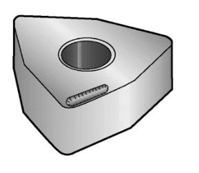
Crater wear results from a combination of diffusion and decomposition (at high cutting speeds) and abrasive wear (at low cutting speeds). The heat generated by workpiece chip production causes the carbide particles in the tool substrate to decompose, and carbon diffuses into the chip. This leads to the formation of “craters” on the tool’s rake face. As these craters enlarge, they may eventually cause chipping of the tool’s secondary edge or accelerate secondary edge wear. Crater wear manifests as crater or point wear shapes on the rake face. It is particularly pronounced when machining abrasive materials such as cast iron or materials with high surface hardness (e.g., forged workpieces).
Strategies to Address Crater Wear
To minimize crater wear, the following measures can be taken:
- Use coatings containing thick layers of alumina oxide: These coatings can provide additional protection, reducing direct contact between the tool and workpiece material, thus reducing wear caused by high temperatures and chemical reactions.
- Properly use coolant to reduce cutting temperatures.
- Reduce cutting speed and feed rate: Cutting at lower speeds and feeds can reduce heat and pressure on the tool, thus reducing the rate of crater wear. However, this may not align with production needs as it adversely affects machining cycles.
3.Built-Up Edge (BUE) Analysis
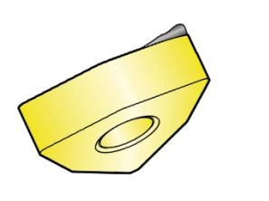
Built-up edge (BUE) forms due to adhesion of workpiece material to the cutting edge at high pressure and sufficiently high temperature. This adhesion typically occurs under conditions where there is a chemical affinity, high pressure, and adequate temperature in the cutting zone. BUE formation leads to accumulation of workpiece material near the tool’s rake face and cutting edge, forming hardened deposits. Eventually, the BUE can fracture, carrying away part of the cutting edge, leading to tool chipping and rapid secondary edge wear.
When Does BUE Occur?
BUE typically occurs under the following conditions:
- When machining materials with strong adhesion, such as non-ferrous metals, superalloys, and stainless steel.
- During operations with slow cutting speeds and feed rates. BUE appears as shiny material portions on the cutting edge or secondary edge of the tool. They cause small pits or craters to appear on the tool’s rake face and eventually lead to chipping of the cutting edge.
Improvement Measures for BUE
- Increase cutting speed and/or feed rate: This helps reduce the time material spends adhering to the tool’s rake face, thus reducing BUE formation.
- Choose blades with sharper geometry and smoother rake faces: This helps reduce the likelihood of material adhesion and improves cutting efficiency.
- Properly apply coolant and increase coolant concentration: Coolant can lower the temperature of the cutting zone, reduce material adhesion, and prevent BUE formation.
4.Microchipping Analysis
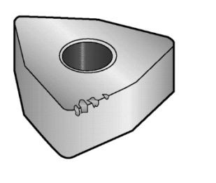
Microchipping occurs due to mechanical instability or cracking in the cutting material. Microchipping of the cutting edge is usually caused by vibration from the workpiece, machine tool, or tool itself. Hard inclusions on the workpiece surface and interrupted cutting can lead to localized stress concentration, resulting in cracks and microchipping of the cutting edge. Microchipping appears as small fractures of material on the cutting edge and is common in non-rigid conditions. Materials with hard particles (such as precipitation-hardened materials) can also cause microchipping of the cutting edge.
Improvement Measures for Microchipping
To minimize microchipping wear, the following corrective measures can be taken:
- Proper machine tool setup: Ensure machine tool stability and reduce vibration.
- Reduce bending deformation: Minimize bending in the machine tool and tool system to improve rigidity.
- Use tougher materials and more robust blade geometries: Choose tools with better impact resistance.
- Reduce feed rate (especially at entry and exit points) and increase cutting speed. (Also see corrective measures to prevent BUE.)
5.Thermal Mechanical Failure Analysis
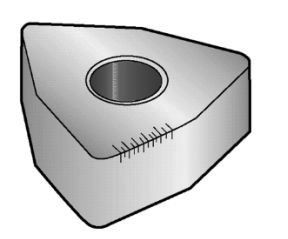
Thermal cracking is caused by the combined action of:
- Thermal load (high temperature in the cutting zone)
- Thermal changes or gradients (temperature changes at the cutting edge) Stress cracks develop approximately perpendicular to the cutting edge, eventually causing the loss of hard alloy portions and edge fracture. Thermal cracking is mainly observed in milling and rotary machining with interrupted cutting. Intermittent flow of coolant can lead to thermal cracking.
Improvement Measures for Thermal Mechanical Failure
- Proper application of coolant: Coolant can help reduce the temperature of the cutting zone, reducing thermal cracking.
- Choose tougher materials: Use tools with better thermal stability.
- Reduce cutting speed and feed rate: This helps reduce the heat generated in the cutting zone.
- Use geometries that reduce heat generation.
- Consider different machining methods (ratio of cutting time to non-cutting time): Adjust machining strategies to reduce the duration of tool exposure to high temperatures.
6.Plastic Deformation Failure Analysis
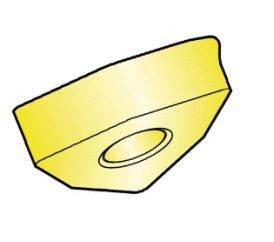
Thermal overload is the primary cause of plastic deformation. Excessive heat softens the carbide binder (cobalt). Subsequently, due to mechanical overload, pressure on the cutting edge causes deformation or drooping at the tip, ultimately leading to chipping or rapid flank wear.
Plastic deformation appears as a deformed cutting edge. Careful observation is required, as plastic deformation on the cutting edge may closely resemble flank wear.
Improving Plastic Deformation Failure
Plastic deformation can be anticipated in situations where cutting temperatures are high (due to high speeds and feeds) and the workpiece material itself has high strength (such as hardened steel or surfaces subjected to strain hardening, and superalloys).
- Proper application of coolant
- Reducing cutting speed and feed rate
- Using cutting tools with larger corner radii
- Selecting harder, more wear-resistant materials
By implementing these measures, plastic deformation can be effectively reduced, enhancing tool durability and machining efficiency.

