Cemented carbide has the edge of high hardness, good wear resistance, corrosion resistance and a small coefficient of thermal expansion. It is widely used in the manufacture of precision molds such as optical glass forming, metal drawing, and wear-resistant and corrosion-resistant parts. Cemented carbide mold not only has a long service life, more than ten times or even hundreds of times that of steel mold, but also has a very high surface quality of products. The glass lens and other parts of injection molding can meet the requirements of optical surface quality.
Cemented carbide is typically hard to machine material due to its poor machinability. Grinding and EDM are two of the most commonly used machining methods of cemented carbide die. With the appearance of CBN, diamond and other superhard tools, it is possible to directly cut cemented carbide, which attracts more and more attention. Foreign scholars have carried out more research. B. bulla et al. Analyzed the influence of machining parameters on the surface profile of cemented carbide in diamond turning. After obtaining the optimal machining parameters, further studied the influence of tool geometry on the surface roughness and tool wear. N. Suzuki et al. Carried out diamond ultrasonic elliptical vibration turning experiments on cemented carbide. It was found that the surface quality of ultrasonic elliptical vibration turning is better than that of ordinary turning, and the tool wear is smaller. Through the experiments, the hard alloy dies such as micro prism and spherical lens with optical surface quality were also machined.
Es una se?al importante medir el nivel de fabricación del troquel nacional para fabricar el troquel de carburo cementado preciso, complejo y de larga duración. La tecnología de microfresado tiene las ventajas de una alta eficiencia de mecanizado, una amplia gama de materiales de mecanizado, mecanizado de formas tridimensionales complejas, alta calidad superficial, etc. Es muy adecuado para mecanizar microtroqueles y micropiezas de carburo cementado y tiene una amplia perspectiva de aplicación. En este documento, las herramientas recubiertas de diamante se utilizan para el microfresado de carburo cementado. Se analizan la fuerza de corte, la calidad superficial y el desgaste de la herramienta.
Test equipment and experiment schedule of PDC micro milling
The self-built high-precision micro milling machine tool (see Figure 1) is used. The machine tool is specially designed for micro milling of small and micro parts. It is composed of marble bed, feed mechanism, high-speed air flotation spindle, motion control system based on PMAC, etc. Due to the small diameter of micro milling cutter, it is not easy to achieve an accurate tool setting. The machine tool is equipped with a microscope tool setting system, which can also be used to monitor the micro-milling process online.
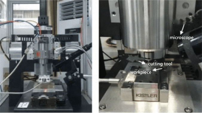
Figure 1 micro milling machine
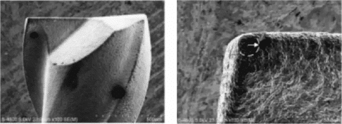
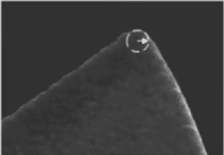
Use diamond coated micro milling cutter with spiral edge (see Fig. 2a). The base material of the cutter is hard alloy, and a layer of diamond film is coated by chemical vapor deposition (CVD). The handle diameter is 6mm, the blade diameter is 1mm, the blade length is 2mm, the front angle of the tool is 2 °, the back angle is 14 °, and the spiral angle is 35 °. The tool tip arc radius γ ε measured from the SEM side view is about 11 μ m (see Fig. 2b); the tool edge arc radius γ β measured from the SEM top view is about 8 μ m (see Fig. 2C).
(a) (b)
(c)
Figure 2 diamond coated micro milling cutter
Diamond coated tools are used to mill the straight grooves under different machining parameters. Before the test, the surface of the workpiece is polished, then fixed and clamped on the measuring instrument, and the sampling frequency is 20kHz. All tests are conducted under dry cutting conditions. See Table 1 for micro-milling test parameters. The spindle speed n is fixed at 20000r / min, the milling depth AP is 2 μ m and 4 μ m, and the feed rate of each tooth FZ is 0.3-1.5 μ M. After the test, ultrasonic cleaning machine was used to clean the workpiece. Mahr surface roughness meter was used to measure the machined surface roughness and micro profile curve along the feed direction. The machined surface morphology and tool wear morphology were observed by SEM.
Test results and analysis of PCD micro milling
Milling force signal is an important parameter to monitor the milling process, which can reflect the tool wear status and machining surface quality in real-time. In the milling process, the cutting thickness changes continuously, which increases from zero to the maximum and then decreases to zero periodically with the rotation of the milling cutter, resulting in the wave trough and wave peak of the milling force signal. From the wave form of the milling force signal, we can observe the abnormal behaviors such as uneven cutting and vibration in the process of machining.
Fig. 3 is a waveform diagram of milling force signal measured by test, where Fx is the main cutting force, Fy is feed force, and Fz is axial force. It can be seen from the waveform of milling force that the amplitude of axial force Fz is the largest in the three components of milling process, far greater than the other two components, followed by the main cutting force Fx and the minimum feed force Fy. The reason is that the milling depth AP in micro milling is very small, which is far smaller than the radius of tip arc γ ε of micro milling cutter. Only a small part of the bottom of tip arc is actually involved in cutting, which is equivalent to the cutting with a small main deflection angle, resulting in a large axial milling force component.
For every rotation of the milling cutter, two symmetrical cutting edges will successively participate in cutting, which shows two wave peaks in the milling force signal period. It can be seen from the oscillogram that the amplitudes of the two peaks are not the same, and the amplitudes of the first half period are obviously larger than the second half. This shows that in the actual milling process, the cutting thickness of two cutting edges of double tooth milling cutter is different, one cutting edge has more materials, the other cutting edge has less materials, resulting in uneven milling phenomenon. Serious non-uniform Milling will cause the fluctuation of milling force, increase the vibration in the process of machining, which is not conducive to the stability of micro milling.
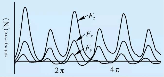
Figure 3 micro milling force signal waveform
The milling forces under different micro milling parameters are recorded during ﹣ test. The peak value of milling force corresponding to the maximum cutting thickness in the tool rotation cycle is taken as the test result, and the measurement results of X, y and Z components are shown in Figure 4. At the same milling depth, the milling force increases with the increase of the feed rate FZ of each tooth. The main cutting force Fx and the feed force Fy rise relatively gently. When the milling depth is ap=2 m and 4 m, the main cutting force Fx rises from 0.44N and 0.92N to 1.34N and 2.05N respectively, and the feed force Fy increases from the 1.34N and the second to the “Ho” and “the”; the axial force increases by a large amplitude, from the “Qi” and “the” to “the”. Similarly, the increase of milling depth will also lead to the increase of milling force. The axial force FZ in the three-way component is sensitive to the milling parameters. The reason is that the feed rate of each tooth FZ in micro milling is smaller than the edge arc radius γ β of the micro milling cutter, which makes the contact area between the back face of the bottom edge of the micro milling cutter and the workpiece relatively large, and the friction force on the back face accounts for a large proportion in the milling force.
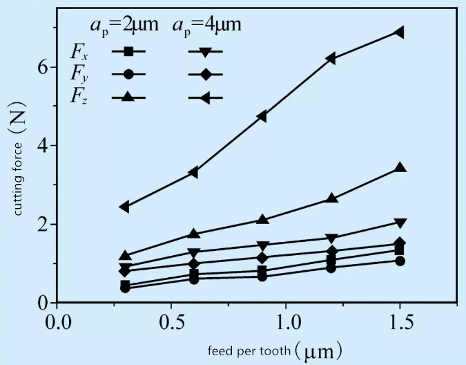
Fig. 4 curve of milling force changing with machining parameters
Surface quality of PCD micro milling
Cemented carbide is a kind of hard brittle material. In traditional cutting, the hard brittle material is usually removed in the form of brittle fracture, which results in brittle failure defects on the machined surface and affects the quality of machined surface. The results show that when the machining parameters are controlled so that the cutting thickness is less than a certain critical value, the brittle material can also have plastic deformation, and the smooth ductile machining surface is obtained, which is called ductile cutting. Figure 5 shows the surface morphology and profile curve of micro milled cemented carbide at AP = 2 μ m and FZ = 1.2 μ M. It can be seen from the figure that the machining surface morphology is mainly the reflection of tool geometry, with clear tool mark texture distributed. From the contour curve, the feed tool mark of the tool teeth can be observed, and there is almost no brittle failure defect. In micro milling, the actual cutting thickness is very small, which can realize the ductile cutting of cemented carbide. The cemented carbide material is removed in the way of plastic deformation to obtain good machining surface quality.
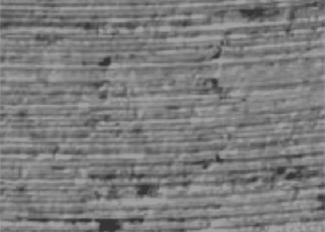
(a)geometry of surface
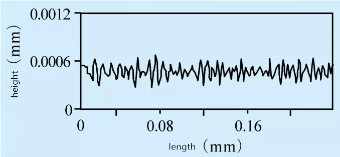
(b) contour curve
Figure 5 machined surface morphology and profile
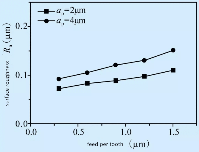
Fig. 6 shows the curve of surface roughness Ra of micro milling cemented carbide with machining parameters. It can be seen from the figure that the Ra value of the machined surface roughness of cemented carbide is very small due to the ductile cutting in micro milling. The surface roughness Ra increases with the increase of feed per tooth AP and milling depth FZ, but the effect of feed per tooth on surface roughness is greater than that of milling depth. When AP = 2 μ m and FZ = 0.3 μ m, the minimum surface roughness is 0.073 μ m; when AP = 4 μ m and FZ = 1.5 μ m, the maximum surface roughness is 0.151 μ M.
(b) contour
Figure 6 shape and outline of machined surface
Fig. 6 shows the change curve of surface roughness Ra of micro milling cemented carbide with machining parameters. It can be seen from the figure that the Ra value of the machined surface roughness of cemented carbide is very small due to the ductile cutting in micro milling. The surface roughness Ra increases with the increase of feed per tooth AP and milling depth FZ, but the effect of feed per tooth on surface roughness is greater than that of milling depth. When AP = 2 μ m and FZ = 0.3 μ m, the minimum surface roughness is 0.073 μ m; when AP = 4 μ m and FZ = 1.5 μ m, the maximum surface roughness is 0.151 μ M.

(a) (b)
(c)
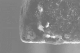
Diagram.7 micro geometry of wearing on cutting tool
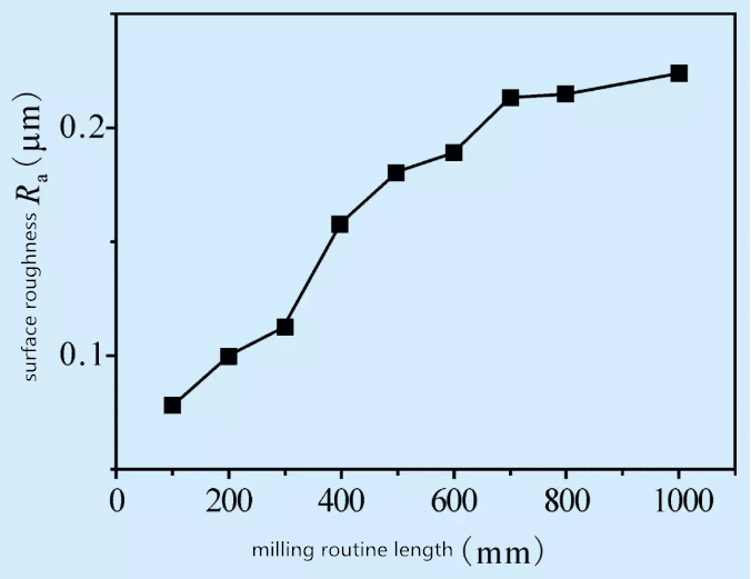
Diagram.8 impact of milling length on surface roughness
Figure 8 shows the curve of surface roughness changing with micro milling path. It can be seen from the figure that the surface roughness Ra increases gradually with the increase of milling path. When the milling distance reaches 700m m, the surface roughness increases greatly; when the milling distance exceeds 700mm, the increase of surface roughness slows down; when the milling length is 1000mm, the surface roughness Ra reaches 0.224 μ M. After the tool wear, not only the milling force increases, but also the extrusion and friction of the workpiece become more serious, which increases the possibility of brittle failure of cemented carbide materials, causes brittle failure defects on the machined surface, worsens the machined surface quality, and increases the surface roughness.
Conclusion so far
(1) because the milling depth is far less than the radius of the tip arc, only the bottom of the tip arc is actually involved in the cutting, resulting in a large axial component. In the micro milling process of diamond coated double tooth milling cutter, there is a phenomenon of non-uniform milling, and the milling force increases with the increase of feed per tooth and milling depth.
(2) micro milling is very small, which can realize ductile cutting of cemented carbide and obtain good machining surface quality. The surface roughness Ra increases with the increase of feed per tooth and milling depth.
(3) results in uneven wear of two blades and serious wear of bearing blades. The surface roughness increases with the increase of milling path.

